The three main goals of this activity are to:
- Test and troubleshoot your Gripper
- If needed, adjust your Gripper
- Get familiar with scripting to make the Gripper pick up and set down objects
Parts
(1) Resistor - 220 Ω (red-red-brown-gold)
(1) 3-pin header
(1) Jumper wire - red
(1) Jumper wire - black
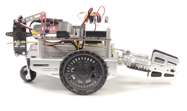
(1) cyber:bot robot with micro:bit v2, and with the Gripper kit installed following the instructions in these chapters:
- Build your cyber:bot (Rev C Board)
- Upgrade Your cyber:bot with Feedback 360° Servos
- Gripper 3.0 Assembly Instructions (Again, do not plug the Gripper servo into any of the servo ports yet.)
Circuit
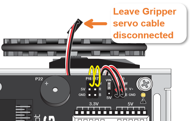
- Leave the Gripper servo cable disconnected for now.
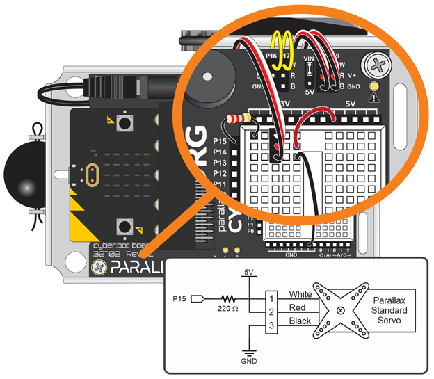
- Build a servo port on the breadboard that’s connected to P15 using the 3-pin header, 220 Ω resistor, and red and black jumper wires.
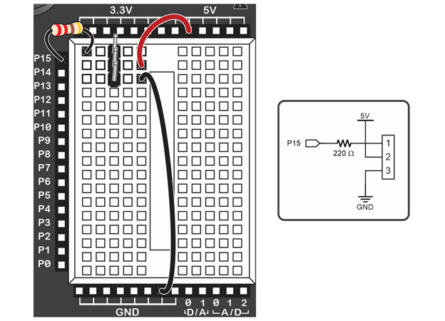
- Connect the Gripper servo to the P15 servo port you just built. Then check your connections to make sure that the servo cable's:
- White wire is connected to the same breadboard row as the 220 Ω resistor.
- Red wire is connected to the same breadboard row as the 5 V jumper wire.
- Black wire is connected to the same breadboard row as the GND jumper wire.