The cyber:bot robot's drive motors are Parallax Continuous Rotation Servos. They control wheel rotation speed and direction in response to very specific patterns of high/low voltage signals.
In this activity, you will first check labels on the servos to identify whether they were factory centered, or if they need to be manually centered with a screwdriver while the micro:bit runs a certain script.
If the servos are factory centered, you will save the screws for attaching the wheels and then skip to the next activity.
If the servos need to be manually centered, you will continue all the way through this activity.
Identify the Servos
First, let's check the labels on the servos in your kit and then decide what to do next.
- If your servo has a part number of 900-00040, then:
- Save the two plastic screws that came in a sub-bag with each servo. You will need two of these screws to attach the cyber:bot’s wheels to the servos, and it is good to keep the second pair to have spares.
- Skip to the next activity: Build the chassis. (Your servos are already factory centered, and you do not need to follow the instructions for manual centering on this page.)
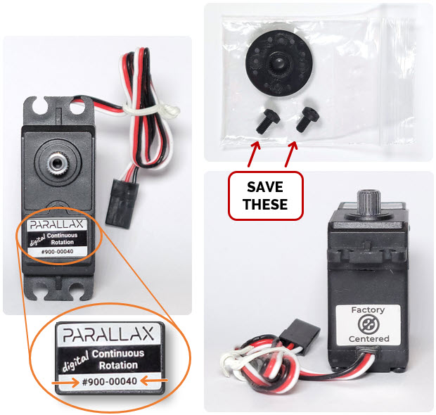
- If your servo has a part number of 900-00008, or no part number at all, continue here.

Parts Required
- (1) Assembled cyber:bot board, with micro:bit module installed from prior step
- (2) Continuous rotation servos
- (1) Battery pack
- (5) AA batteries
- (1) USB A to microB cable
Tool Required
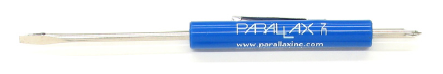
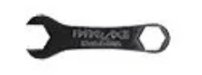
If the Procedure checklist says to remove the servo from the cassis, use these tools that come in the cyber:bot Robot kit:
(1) Parallax screwdriver, or a different Phillips #1 point screwdriver with a 1/8″ (3.18 mm) or smaller shaft.
(1) Parallax Combination Wrench (#700-10025), or a 1/4" combination wrench.
cyber:bot Library Required!
- If you have not done so already, download the cyber:bot library and add it to your micro:bit module's file system. Just follow the steps in Add modules to your micro:bit and then return here.
The cyber:bot Board's 3-position Power (PWR) Switch
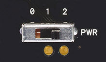
The cyber:bot board has a three-position power switch, labeled PWR. It allows you to choose whether or not to supply power to the servos when you supply power to the rest of the cyber:bot board. Here are guidelines:
- Position 0: ALWAYS use position 0 for building or modifying circuits on the breadboard or 3-pin/Servo ports. It is also good for flashing scripts. Position 0 turns off power to the whole cyber:bot board. If the micro:bit is plugged into USB, you can still flash non-robot scripts, and they will wait for the PWR switch to be changed to 1 or 2. You can also flash and run non-robot scripts with the PWR switch set to 0.
- Position 1: Good for flashing scripts and powering breadboard circuits and the piezospeaker port. Position 1 powers the Propeller system, the piezospeaker port, and sockets along the breadboard, but not the 3-pin/Servo ports, so your cyber:bot won’t roll away the moment you program it. Position 1 also powers the micro:bit independent of its USB port.
- Position 2: ONLY use 2 when you are ready for your robot to move. NOT good for flashing scripts. Position 2 powers all the circuits on the board, including the 3-pin servo ports, and also the micro:bit independent of its USB port.
- Set the PWR switch to 0.
Connect the Servos
The servo cables plug into the 3-pin P18 and P19 3-pin headers. These headers, sometimes called servo ports, are above the white breadboard.
- Ignore the Left Servo and Right Servo labels for now.
- Align a servo cable plug so that the white wire is near the board edge, and the black wire is by the pin labeled GND.
- Carefully line up the 3 holes in the servo plug with the 3 pins below the P19 label.
- Press the servo plug onto the P19 port. Make sure it is pressed all the way down so that no pin metal is visible.
- Repeat with the other servo connected to the P18 port.
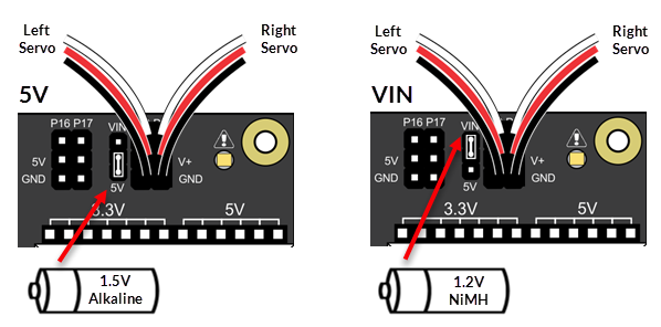
Voltage Selection Jumper
There is a smaller 3-pin header to the left of the P18 servo port. It is called a shunt jumper, and selects servo supply voltage by connecting two of the three pins between the VIN and 5V labels. The 5V setting (lower two pins) limits the servo supply voltage to 5V, regardless of the input voltage. The VIN setting (upper two pins) supplies the servo with the 5-cell battery pack's voltage.
The Continuous Rotation Servos need 4 to 6 VDC to operate. So, the setting you should use depends on the kind of batteries you have.
- 1.5V alkaline batteries: Use the 5V setting. (1.5V x 5 batteries = 7.5V, which is too much.)
- 1.2V NiMH rechargeable batteries. Use the VIN setting. (1.2V x 5 batteries = 6V, which is just right)
- If needed, lift the shunt jumper off of the pins and place it back on again so it connects the center pin and the pin for the correct voltage for your type of batteries.
Missing a Voltage Selection Jumper? Replacements are available - contact our sales department to order part #452-00043; there are three per board.
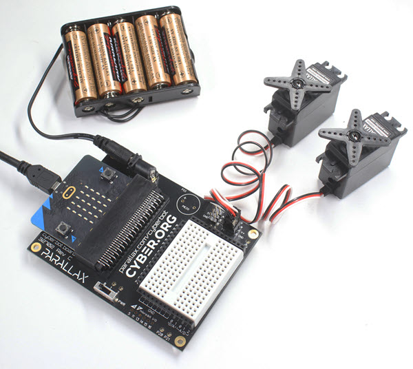
Add the Batteries
- Add the 5AA batteries to the battery pack.
- Plug the battery pack into the power jack on the cyber:bot board.
Connect the USB Cable
- Connect the micro:bit to the computer with the USB cable, if it isn't already connected.
Complete System, Ready!
Test and Center the Servo Connected to P18
If a servo has not yet been centered, it may turn, vibrate, or make a humming noise when it receives the “stay-still” signal. It is best to center the servos before assembling the cyber:bot; they are more difficult to adjust after assembly.
- Watch this short video, then follow the step-by-step instructions below.
- In a Google Chrome or Microsoft Edge browser, go to python.microbit.org to open the micro:bit Python Editor.
- Make sure the cyberbot.py module is added to your project.
(See Add modules to your micro:bit.) - Delete all of the default script the editor opens with and enter left_servo_stay_still (below) in its place.
- Set the Script Name field to left_servo_stay_still, then click Save.
(See Save & Edit Scripts.) - Make sure to include the line from cyberbot import *.
- Flash left_servo_stay_still to your micro:bit with the Send to micro:bit button.
(See Flash Scripts with Python Editor.)
Example script: left_servo_stay_still
# left_servo_stay_still

from cyberbot import *

bot(18).servo_speed(0)
- Set the cyber:bot’s power switch to 2 to provide power to the servos.
- If the servo connected to P18 turns instead of staying still, it needs to be adjused.
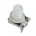
- Find the adjustment port. It's a hole near where the servo cable attaches to the servo's black case.
- Use a Phillips screwdriver to gently adjust the potentiometer in the servo as shown below.
Don’t push too hard!
Turn the potentiometer gently in each direction to find the setting that makes the servo stop turning, humming, or vibrating.
Did you know?
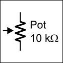
A potentiometer is a device that provides variable electrical resistance. Some potentiometers have a knob for adjusting the resistance, the one below, which also has pins for plugging into a breadboard. Others are adjusted with a screwdriver, like the ones in the servos. Others may have a sliding bar. Either way, the schematic symbol for a potentiometer is the same.
Your Turn – Center the Servo Connected to Pin 19
- Repeat the process to center the servo plugged into the P19, using the script right_servo_stay_still.
Example script: left_servo_stay_still
# right_servo_stay_still

from cyberbot import *
bot(19).servo_speed(0)
- Set the PWR switch to 0.
- NOW DISCONNECT YOUR SERVOS AND BATTERY PACK FROM THE BOARD!