Jump to navigation
Install the F360 Servos
Reassembly with Feedback 360° Servos
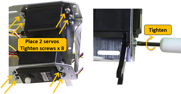
- Insert each Feedback 360° servo into the chassis from the inside, and make sure the output spline is closer to the tail wheel than it is to the front of the chassis.
- Tighten the eight 3/8” screws and nuts that hold each servo to the chassis.
- Do not feed any cables through the chassis yet.
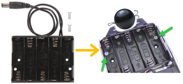
- Re-insert the battery pack into the chassis and tighten each Nylon screw. Tighten only very lightly and make sure that the top of the screw head does not go below flush with the inside surface of the battery pack.
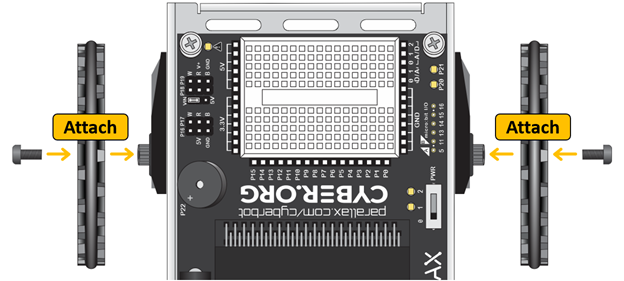
- Push the wheels back onto the Feedback 360° servo splines.
- Use the plastic screws that came with the Feedback 360° servos to attach the wheels to the servo output splines.
- DO NOT OVERTIGHTEN. The screws should be just barely fingertip tight.
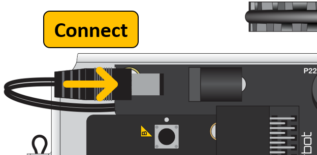
- Feed the battery barrel pack plug through the hole in the center of the chassis.
- Pull the plug between the two standoffs attached to the tail wheel end of the chassis, and reconnect it to the barrel jack.
- Do not put batteries back in yet.
Circuit
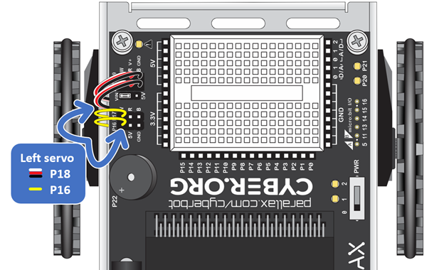
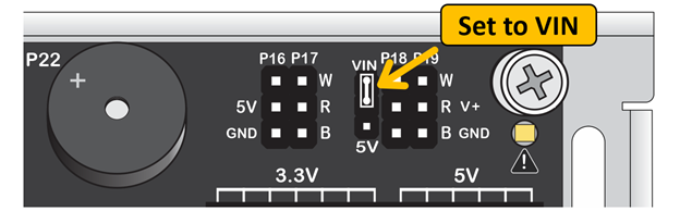
- Make sure the shunt jumper next to the P18 servo port is set to Vin.
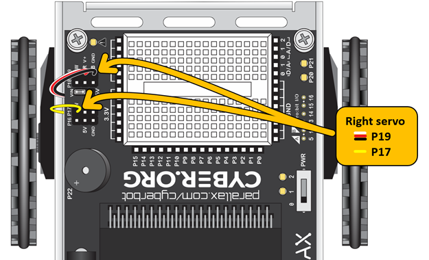
- Find the right servo in the diagram below, and pull its yellow and white/red/black cables through the hole in the center of the chassis.
- Plug the white/red/black cable into the P19 port, and make sure the white wire is closest to the P19 label at the outer edge of the board..
- Plug the yellow wire onto the P17 pin that’s closest to the P17 label at the outer edge of the board.
- Repeat for the left servo, plugging its white/red/black cable onto the P18 servo port,
- Plug the left servo's yellow signal wire onto the P16 pin, closest to the the P16 label at the outer edge of the board.