Hardware Setup
- Set the cyber:bot board's power (PWR) switch to Position 0.
- Make sure the battery holder is loaded with 5 AA batteries.
- Make sure the battery holder's barrel plug is firmly plugged into the cyber:bot board's barrel jack.
- Connect your micro:bit module to your computer with a USB cable.
Software Setup
- In a Google Chrome or Microsoft Edge browser, go to python.microbit.org to open the micro:bit Python Editor.
- Right-click the link below for the file cyberbot_feedback_360_diagnostic.hex, and select Save link as…
cyberbot_feedback_360_diagnostic.hex
- Save the file, and then Open it with the micro:bit Python Editor.
Note: The script was created by entering the python script below and adding the cyberbot.py and feedback360.py modules to the Project Files as shown in Add modules to your micro:bit. The project name was set to cyberbot_feedback_360_diagnostic before saving it as a .hex file as shown in Save & Edit Scripts.
Tests
These tests — and any wiring corrections you may need to do — will need to be repeated until you see the “The servos have passed all the tests!” message.
- Click Send to micro:bit.
- Set the cyber:bot board's PWR switch to 2.
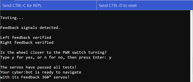
- Click Open Serial, and follow the prompts in the serial monitor. They will resemble what's shown above.
- If there are any connection problems, it will report them to you and tell you to consult the Troubleshooting Guide below. Look up the problem in the troubleshooting guide and follow the suggested steps.
- To restart the script for another test after you have corrected a potential problem, just click Send to micro:bit again. Sometimes it’ll catch a new issue after you have resolved the current one, so keep repeating until it passes all the tests.
- As a final step, the diagnostic will ask if the wheel closer to the PWR switch is turning. If the answer is yes, type y and press Enter. If the wheel closer to the servo ports is instead the one that is turning, type n (for no) and press Enter.
- Continue following the prompts until you see the “The servos have passed all the tests!” message. Then, skip to the next activity.
Troubleshooting Guide
There are several different types of error messages. Find the one you see in the sections below, and follow the red checkmarks under it to correct the issue.
Feedback Signal Messages:
No feedback signal to P16.
No feedback signal to P17.
Problem with feedback signal(s).
If you see all three feedback messages:
- If PWR is set to 1, set it to 2.
- Use the Circuit section as a reference and try these:
- Make sure the 3-wire servo cables are connected with white wires closest to the P18 and P19 labels.
- Make sure that the yellow wires are each connected to the topmost pin of each 3-pin servo header, closest to the P16 and P17 labels.
- Check to make sure the shunt jumper between the P17 and P18 servo ports is present and set to VIN.
If you only see two of the three messages listed above, use the Circuit section as a reference and try these:
If there’s no feedback signal to P16:
- Check the yellow wire connected to the P16 port. It should be connected to the topmost of the three pins, closest to the P16 label.
- Check the servo cable connected to the P18 port. Its white wire should be connected closest to the P18 label (then the red wire goes to the middle pin and the black wire to the bottom pin.
If there’s no feedback signal to P17:
- Check the yellow wire connected to the P17 port. It should be connected to the topmost of the three pins, closest to the P17 label.
- Check the servo cable connected to the P19 port. Its white wire should be connected closest to the P18 label (then the red wire goes to the middle pin and the black wire to the bottom pin.
Swapped Wires or Cables Message:
Either yellow wires are swapped with each other
or servo cables are swapped with each other.
If you see this message:
- Follow the 3-wire cable from the servo closer to the PWR switch, and make sure it’s connected to the P19 port. If it’s connected to P19, then swap the two yellow wires with each other. If it’s connected to the P18 port, swap the servo cables with each other.
Wheel Turning Message:
The wheel closer to the PWR switch should be turning.
If you see this message:
It means that the yellow wires are swapped with each other, AND the servo cables are swapped with each other.
- Connect the 3-wire servo cable that was connected to the P19 port to the P18 port, and vice-versa.
- Connect the yellow feedback cable that was connected to P16 to P17 and vice-versa.
Wheel Not Turning Messages:
The servo connected to P18 does not seem to be turning.
The servo connected to P19 does not seem to be turning.
If you see this message:
- Set PWR to 0.
- Slowly and gently turn both wheels. If one turns with some resistance (due to the gears), that’s fine. If one feels locked, contact support@parallax.com.
- Inspect the white wire where it connects to the servo plug. If it looks like the white wire has been pushed part way out of the plug, push it back in. It should snap into place and not get pushed out again.
- If this message persists, contact support@parallax.com.
Slow Turning Messages:
The servo connected to P18 is turning too slowly.
The servo connected to P19 is turning too slowly.
If you see this message:
- Set PWR to 0.
- Slowly and gently turn both wheels. If one turns with some resistance (due to the gears), that’s fine. If one has a really high resistance compared to the other, contact support@parallax.com.
- The VIN/5V jumper between the P17 and P18 servo ports might be set to 5V. It should be set to VIN.
- If the jumper is covering the lower two pins (5V and the center pin), pull it up off the two pins, then push it down over the upper two pins (VIN and the center pin)
- If this message persists, contact support@parallax.com.
Fast Turning Messages:
The P18 servo is turning unusually fast.
The P19 servo is turning unusually fast.
If you see this message:
- Make sure you are not using 3 V rechargeable batteries.
- If you are, in fact, using 1.5 V alkaline or 1.2 V NiMH batteries, use a # to comment the wait_for_reset() call below these two statements in the script:
print('The P18 servo is turning unusually fast.')
print('The P19 servo is turning unusually fast.')